HVAC water system equations are formulas that relate the water flow rate, temperature difference, heat load, and pump power of a heating or cooling system that uses water as the heat transfer medium. These equations are useful for designing and optimizing HVAC systems that use water chillers, cooling towers, evaporators, and condensers.
One of the most basic HVAC water system equations is the total heat load equation, which states that the heat load (h) is equal to 500 times the product of the water flow rate (q) and the temperature difference (dt) between the inlet and outlet of the system. This equation can be used to calculate the heat load of any water system, whether it is for heating or cooling purposes.
Another set of HVAC water system equations are the evaporator and condenser water flow rate equations, which are used to determine the required water flow rate for a given air conditioning load and temperature difference. The evaporator water flow rate equation states that the evaporator water flow rate (q_evap) is equal to 24 times the ratio of the air conditioning load (h_evap) and the temperature difference (dt) across the evaporator2. The condenser water flow rate equation states that the condenser water flow rate (q_cond) is equal to 30 times the ratio of the air conditioning load (h_cond) and the temperature difference (dt) across the condenser. These equations can be used to size the water pumps and pipes for the evaporator and condenser circuits of a water chiller system.
A third set of HVAC water system equations are the pump laws, which are used to calculate the pump power, speed, and head for a given water flow rate and pressure. The pump laws state that the water flow rate (q) is proportional to the pump speed (rpm), the pump head (hd) is proportional to the square of the pump speed, and the pump power (bhp) is proportional to the cube of the pump speed. These equations can be used to select the appropriate pump for a water system, or to adjust the pump speed and power for different operating conditions.
Total Heat Load Equation
The total heat load (Q) in an HVAC system is the sum of the sensible heat load (Qs) and the latent heat load (Ql).
The equation is given by:
The sensible heat load is the amount of heat required to change the temperature of a substance without changing its phase, while the latent heat load is associated with phase changes.
Sensible Heat Load Formula
Sensible heat load is calculated using the formula:
where:
is the mass flow rate of air (in pounds per hour or kilograms per second),
is the specific heat of air (in BTU/lb·°F or J/kg·°C),
is the temperature difference (in °F or °C).
Latent Heat Load Formula
Latent heat load is calculated using the formula:
where:
is the mass flow rate of water vapor (in pounds per hour or kilograms per second),
is the latent heat of vaporization (in BTU/lb or J/kg).
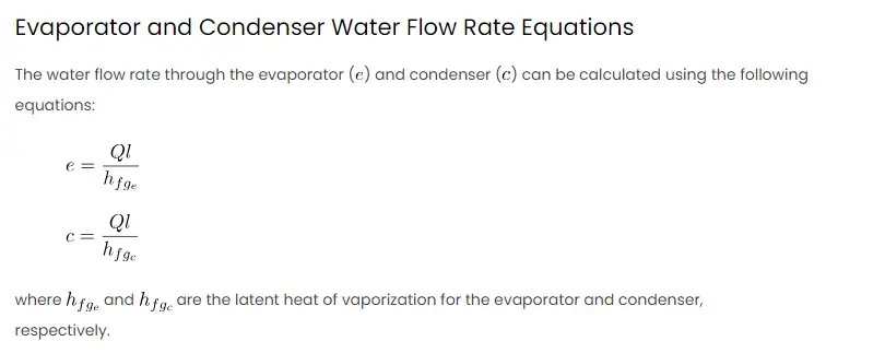
Evaporator and Condenser Water Flow Rate Equations
The water flow rate through the evaporator () and condenser (
) can be calculated using the following
equations:
where and
are the latent heat of vaporization for the evaporator and condenser,
respectively.
Pump Laws
The pump laws describe the relationship between pump speed, impeller diameter, and pump head. The affinity laws are
useful for estimating how changes in pump speed or impeller diameter affect the system. The affinity laws are
given by:
where is flow rate,
is pump head,
is impeller diameter, and
is pump speed.
Basic Theory
Before diving into the Excel formulas, it’s crucial to understand the basic theory behind HVAC water systems. Heat loads, flow rates, and pump characteristics are interconnected and must be carefully balanced to ensure optimal system performance.
Procedures
- Total Heat Load Calculation:
- Input the sensible and latent heat loads.
- Use the total heat load equation to find the overall heat load.
- Evaporator and Condenser Water Flow Rates:
- Input the latent heat of vaporization for both evaporator and condenser.
- Use the respective flow rate equations to calculate water flow rates.
- Pump Laws:
- Input initial pump conditions (speed, head, impeller diameter).
- Utilize the pump laws to estimate the effect of changes in pump speed or impeller diameter.
Example
Consider an HVAC system with a total heat load of 50,000 BTU/hr, a latent heat load of 20,000 BTU/hr,
BTU/lb, and
BTU/lb. The initial pump speed is 1,200 RPM, pump head is 40 ft, and impeller diameter is 10 inches.
Excel Table
| Parameter | Value |
|---|---|
| Q | 50,000 |
| Ql | 20,000 |
| 900 | |
| 800 | |
| Pump Speed | 1,200 |
| Pump Head | 40 |
| Impeller Diameter | 10 |
Calculation in Excel
- Calculate total heat load using Excel formula:
=Qs + Ql. - Calculate evaporator water flow rate using Excel formula:
=Ql/h_{fg_e}. - Calculate condenser water flow rate using Excel formula:
=Ql/h_{fg_c}. - Implement pump laws in Excel for different scenarios.
MATLAB Comparison:
Scenario Parameters
Q = 50000;          % Total Heat Load (BTU/hr)
Ql = 20000;         % Latent Heat Load (BTU/hr)
h_fg_e = 900;       % Latent Heat of Vaporization for Evaporator (BTU/lb)
h_fg_c = 800;       % Latent Heat of Vaporization for Condenser (BTU/lb)
pump_speed = 1200;  % Pump Speed (RPM)
pump_head = 40;     % Pump Head (ft)
impeller_diameter = 10; % Impeller Diameter (in)
Calculations
total_heat_load = Q;                % Total Heat Load
evaporator_flow_rate = Ql / h_fg_e; % Evaporator Water Flow Rate
condenser_flow_rate = Ql / h_fg_c;   % Condenser Water Flow Rate
Pump Laws
new_pump_speed = 1500; % Example: New Pump Speed (RPM)

% Applying Pump Laws
new_flow_rate = (new_pump_speed / pump_speed) * evaporator_flow_rate;
new_head = (new_pump_speed / pump_speed)^2 * pump_head;
new_impeller_diameter = (new_pump_speed / pump_speed) * impeller_diameter;
Display Results
fprintf('Total Heat Load: %d BTU/hr\n', total_heat_load);
fprintf('Evaporator Flow Rate: %.2f lb/hr\n', evaporator_flow_rate);
fprintf('Condenser Flow Rate: %.2f lb/hr\n', condenser_flow_rate);

fprintf('\nPump Laws for New Pump Speed (%d RPM):\n', new_pump_speed);
fprintf('New Flow Rate: %.2f lb/hr\n', new_flow_rate);
fprintf('New Pump Head: %.2f ft\n', new_head);
fprintf('New Impeller Diameter: %.2f in\n', new_impeller_diameter);
This MATLAB script defines variables for the scenario parameters and performs the specified calculations, including the pump laws for a new pump speed. The results are then displayed in the MATLAB command window. Note that this is a simplified script, and in a real-world scenario, additional considerations and calculations might be necessary.


